Simple AC PWM Dimmer for Arduino

Here we have designed a PWM dimmer circuit which uses IRF830A (N – CHANNEL 500V – 1.35Ω – 4.5A – TO-220 PowerMESH MOSFET) in a diode bridge used to control the voltage across the bulb with pulse-width modulation (PWM). The power supply voltage for driving the gate is supplied by the voltage across the MOSFET.
By using this project you will be able to control the brightness of a lamp connected to the circuit through serial port.ie the brigntness can be adjusted depending on the commands that we pass through serial port.In this project the following will be the serial port commands that we will be using.
- ‘0’ to Turn OFF
- ‘1’ for 25% brightness
- ‘2’ for 50% brightness
- ‘3’ for 75% brightness
- ‘4’ for 100% brightness
Circuit diagram and description

The power supply voltage for driving the gate is supplied by the voltage across the MOSFET. D6, R5 and C2 form a rectifier. R5 limits the current pulses through D6 to about 1.5 A (as a consequence it is no longer a pure peak rectifier). The voltage across C2 is regulated to a maximum value of 10 V by R3, R4, C1 and D1. An optocoupler and resistor (R2) are used for driving the gate.
R1 is intended as protection for the LED in the optocoupler. R1 also functions as a normal current limiting device so that a ‘hard’ voltage can be applied safely. The optocoupler is anold acquaintance, the CNY65, which provides class-II isolation. This ensures the safety of the regulator. The transistor in the optocoupler is connected to the positive power supply so that T1 can be brought into conduction as quickly as possible. In order to reduce switching spikes as a consequence of parasitic inductance, the value of R2 has been selected to be not too low: 22 kΩ is a compromise between inductive voltages and switching loss when going into and out of conduction.
An additional effect is that T1 will conduct a little longer than what may be expected from the PWM signal only. When the voltage across T1 reduces, the voltage across D1 remains equal to 10 V up to a duty cycle of 88 %. A higher duty cycle results in a lower voltage. At 94 % the voltage of 4.8 V proved to be just enough to cause T1 to conduct sufficiently. This value may be considered the maximum duty cycle. At this value the transistor is just about 100 % in conduction. At 230 V mains voltage, the voltage across the lamp is only 2.5 V lower, measured with a 100-W lamp. Just to be clear, note that this circuit cannot be used to control inductive loads. T1 is switched asynchronously with the mains frequency and this can cause DC current to flow.
Electronic lamps, such as the PL types, cannot be dimmed with this circuit either. These lamps use a rectifier and internally they actually operate off DC.A few remarks about the size of R3 and R4. This is a compromise between the lowest possible current consumption (when the lamp is off) and the highest possible duty cycle that is allowed. When the duty cycle is zero, the voltage across the resistors is at maximum, around 128 V with a mains voltage of 230 V. Because (depending on the actual resistor) the voltage rating of the resistor may be less than 300 V, two resistors are connected in series. The power that each resistor dissipates amounts to a maximum of 0.5 W. With an eye on the life expectancy, it would be wise to use two 1-W rated resistors here.
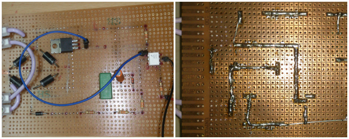
Assembling Technique
Arduino script
int ledPin = 3;
void setup(){
Serial.begin(9600);
Serial.println(“Serial conection started, waiting for instructions…\n0 = Off\n1 = 25%\n2 = 50%\n3 = 75%\n4 = 100%”);
}
void loop (){
if (Serial.available()) {
//read serial as a character
char ser = Serial.read();
//NOTE because the serial is read as “char” and not “int”, the read value must be compared to character numbers
//hence the quotes around the numbers in the case statement
switch (ser) {
case ‘0’:
analogWrite(ledPin, 0);
break;
case ‘1’:
analogWrite(ledPin, 64);
break;
case ‘2’:
analogWrite(ledPin, 128);
break;
case ‘3’:
analogWrite(ledPin, 192);
break;
case ‘4’:
analogWrite(ledPin, 255);
break;
default:
Serial.println(“Invalid entry”);
}
}
}
Download the complete project here


